Engine Gearbox and Clutch

The LS3 crate engine and Tremec Magnum gearbox has arrived.
Slight problems to resolve.
The yoke I had acquired was a 27 spline yoke from the tremec t56 unfortunately it does not fit the magnum gearbox.
The Yoke needed for a magnum transmission is 31 spline as detailed.

Dana Spicer 3-3-5961X
1350 Series Slip Yoke 31 Spline fits Tremec T56 MAGNUM and TKO 600 Transmission
Length to center of u-joint… Dimension #1 = 6 1/2 inches
Barrel Diameter… Dimension #2 = 1 11/16 inches
Barrel Length… Dimension #3 = 4 1/2 inches
U-joint cap diameter… Dimension #4 = 1 3/16 inches
U-joint width… Dimension #5 = 3 5/8 inches
Series… 1350
Spline count… 31

magnum yoke

Good news – called GD and sounds like they have one in stock. Ill order up a full propshaft from GD as soon as I do a trial fit of the engine.

Tried the engine and transmission in for size and works out the prop gap is about 366mm I guess the actual prop length will be something a little shorter than this with an allowance for a bit of clearance on the sliding spline.

Clutch Trial Fit

What on earth was I doing a clutch trial fit for you may well ask, well the truth is I wasn’t  meant to but after fitting the clutch and pressure plate housing I started to do a bit of reading up to find out what the odd looking connection was on the slave cylinder. Whilst searching for information on the slave cylinder fluid input fitting which turns out to be “Quick Disconnect Fitting” I also discovered that I had inserted the pilot bearing the wrong way around. It said nothing on the instructions I received with the installation kit about direction for the pilot bearing and although I did notice it had a slight difference I chose to put it in with the needle bearings visible and closest to the transmission. My logic was simply to get the needle bearings further along the shaft end.

Turns out my logic was wrong and the bearing goes in with the closed end towards the tranny, obvious when you realise that this is the grease seal end.  OK so the clutch has to come back off – no big deal but how the heck will I get the pilot bearing out that i just drifted in with a 3lb hammer?  My first thought was, OK its just going to get butchered out and buy a new pilot bearing but a quick google check and low and behold some genius on youtube had figured out a 3 minute solution. All I had to do was pack the centre of the bearing with grease and insert a close fit (15mm) drift through the centre of the bearing, strike it with a hammer a few times and low and behold the bearing jumps out. Extreme Hydraulic pressure pushes it out from behind – what a good trick –  and it works – youtube to my rescue!DSC_0302

Now on to the problem of that Quick Disconnect which got me searching in the first place. Apparently these fittings are used quite extensively in the USA and the idea is to enable disconnection of the slave cylinder for removal of transmission during clutch service etc. without introducing air into the system so alleviating the need to bleed.DSC_0298

The Quick Disconnect is the big orange part in the picture. The other opening is for the bleed nipple which is lengthy so it can just be bled from the bellhousing opening. I’m going to fit external bleed flexi pipes so I plan to modify both of these fittings. Pretty easy on the bleed side since its just an m10 fitting, so a standard male end of a flexi would work here but the quick disconnect is not so simple since its fitted into the slave cylinder aluminium casing with a flat o ring and groove, held in place with a roll pin. I think the simplest method here may be to cut this orange bit off and have the blank pipe end threaded to m10 with a taper. That way I could fit an m10 female/female extension fitting, effectively replacing the orange part with this.

m10 female

I’ll figure this out over the next couple of days and report my solution here.

Trial fit to get prop lengthDSC_0312

Things are starting to get heavy  LS3 and Tremec Magnum in place.

Engine back out to sort the clutch slave issue here’s a pic of the new fittings. The banjo fitting on top is for the remote bleed flexi this replaces the long brass bleed screw (above). The setup on the lower input shows the new fitting that replaces the ‘quick disconnect’ (orange plug above). It was easier to turn this fitting with a standard male metric brake end as shown, but since I already had my flexi pipe with a male end just adding a standard female/female coupling in between joins it all together.

clutch slave fitting

With this complete I can re-install the engine and gearbox in the chassis.

Brakes

Seem to have all the brake lines connected now… I had a moment of doubt, the brake line fitting kit I obtained (which includes the majority of the brake lines and T junctions), had the same flared ends at each end of the lines ( ie. a double flare).

This is a picture of the double flare (concave) on pipe end and in this circumstance I have no doubt it is correct since it is mating to a male (convex) fitting.  However, at its other end you can see it is going inside a T junction and the T junction is concave internally, therefore I might have expected this length of pipe to have a bubble flare (convex) on opposite end… hmmm curiously all the ends are double flares. DSC_0312.JPG

I wasn’t expecting that and pondered whether to follow this logic for the other connections I had to make myself ie. the ones going into the callipers. I did do a bit of google research on the subject and found some suggestion that double flares can be used in all circumstances (male and female counter ends) and may have better reliability when used in circumstances when the fitting is connected/disconnected repeatedly. (maybe a brake expert can chip in on this one because I’m still unsure).

In the end I decided to follow the same logic as the professionally supplied lines and double flare each end.

DSC_0313

The Jag calliper support brackets I acquired are a little shabby, so my son made me some new ones in stainless steel. Good Job Josh ( I knew he’d come in useful one day….:)).

Handbrake Calipers
Well as much as I was pleased I didn’t have to strip the jag parts myself ( I acquired these from someone’s aborted build ) it does have the odd drawback, here’s one.
I sent the handbrake callipers off to Wards to be refurbished not really knowing some parts are missing.


Once I offered the handbrake cable up I realised the parts where missing some critical bits (the swivel block ends). I then tried to order the ends from Wards only to be told those parts are not available separately, and the ends should never be taken out…
Oh well not to worry – who needs a handbrake.


Body update

Not had much to do lately, simply because I have no other parts… things should start getting real busy soon. Just had confirmation my engine gearbox clutch etc. are all arriving next week. then I can start with engine installation wiring etc. plus Just had confirmation from Andy that body is still on schedule for early May. Sounds like I’m first in the mould after Stoneleigh so lots of action coming shortly. I have to confirm the colour to Andy next week…   out with the RAL chartsral-k5-faecher

Bumpsteer

Setting the bumpsteer was interesting I firstly tried clamping straight edges and using line of sight to keep them parallel. This did identify how far out it was to begin with (quite a bit) but I didn’t feel confident about achieving the best position this way since it was difficult to perceive very small changes.

Out with the trusty Hilti Laser (this is a self-levelling type of laser so I clamped that on the wheel disk fired straight ahead, in the direction of travel onto the garage door a few feet away. After some plotting of curves it quickly becomes obvious that you can’t really do it this way since the observed travel is a combination of bumpsteer together with scrub (the in/out movement of the wheels caused by the wishbone radiuses) and camber change effect (caused by the unequal wishbone lengths).Geometry-Model wishbones

You could use the above method by calculating the amount of scrub then plotting the curve that is created by the radius arm travel Then whilst measuring bumpsteer the best line that could be achieved is the compound curve shown above right. But even then you would also need to account for the camber change that is happening throughout this movement.

The method of shooting the laser perpendicular to the wheel disc is better because this eliminates the scrub effect since the laser will not move “off line” due to scrub, it moves off line only due to bumpsteer. ( plus a bit of vertical change due to camber change).

You could use a mirror clamped flat to the disk and fire the laser at the mirror as has been suggested before but I’m not convinced what the mirror brings to the party, I feel it just complicates the setup.

With a couple of simple clamps fixing the laser approximately perpendicular to the disc at any point will allow exceptionally accurate readings to be made very swiftly – horizontal movement of the laser line only represents the element being induced by the steering arm…. Job done.

The further away you can put the target  the better since any slight movement is exaggerated, in my case I was able to get an almost vertical line at 4m distance that’s definitely zero bumpsteer (well near enough).  Again well done GD for excellent geometry around the steering rack chassis elements. This would not be possible unless everything was in excellent geometric harmony.

Ok that’s the end of this boring bit (Civil Engineers white helmet off – petrol head back in place…..)

Did I mention I was impressed with GD’s chassis geometry J?

As you can see I have been rather milking this part of the build simply because I have no other parts… However things should start getting real busy soon. Just had confirmation my engine gearbox clutch atc are all arriving next week then i can start with engine installation wiring etc. plus body is still on schedule for early May so lots of action coming shortly..


Alignment and geometry

And now the Civil Engineer in me comes out… Prepare to be bored by this bit.

Setting up the caster and cambers on the front and camber on rear is relatively straight forward and well covered elsewhere, however I seemed to find a lot of ambiguity regarding the rear toe set up. Consensus suggests there should be a slight toe setting but how much?

GD suggest “10 minutes (with 10 minute tolerance)” so that suggests 0 to 20 minutes is acceptable?

Haynes manual states rear “wheel alignment Parallel +/-  1/32” or (0.08mm)” they must have a decimal place typo since that’s 0.8mm.     so that suggests acceptable range of -0.8mm to +0.8mm

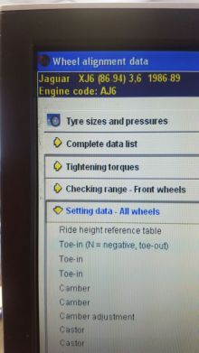
Jaguar Wheel Alignment Data  (from Jaguar dealership see below)

This is helpful, it gives the data 3 ways and clears up a bit of mystery/ambiguity I think.

Toe in    mm 0.8 (+/-0.8)

Toe in   deg 0.10 +/- 0.10

Toe in   deg 0°6’ +/- 6’

I’m going to assume all of these measurements are a combined measurement (ie the total toe between the wheels), so a toe of 10 mins would mean 5 mins at each wheel. Therefore, I’ll aim at 5 minutes/side. Jag data specifies anything between zero and 12mins combined (zero and 6 mins per side).GDs figure of 10 minutes refers to combined toe so that’s 5 minutes per side… Voila everything’s on the same page more or less, I’m happy and your bored!

Geometry-Model

Rather than try to measure 0.8mm over 15” it is much easier to set up a string line system (fine thread or braid is great for this) to measure 3mm over 2.4m (which is a nice distance to gauge an accurate setting), and conveniently is the approx. distance between centreline of rear axle and steering rack so easy to set up a nice square. I have to comment at this stage on the accuracy of the Chassis – so far I have been extremely impressed at the accuracy obtained in manufacturing the chassis, which translates into very little and even shimming of running gear components. I know how difficult this kind of accuracy is to achieve – so “hats off” to GD for their Jig work!

ISL_7954

Couple or recommendations here.

1 – make absolutely sure that the straight edge you use to clamp to the disc, which acts as the alignment throw for the toe measurement, is absoluteley straight and perfectly clamped to the disc. Any tiny amount ‘out of true’ for your staraight edge will make this measurement useless.

2 To adjust the toe use shims between the wishbone carrier bracket and the diff to achieve the desired toe of -3mm at 2.4m away – but I would suggest removing the GD back carrier bracket before making these adjustments. It was my experience that the holes in this bracket are very “tied up” to the shaft diameter therefore it was impossible to correctly adjust the toe with this bracket in place. All you would be doing is inducing stress into the shaft and needle bearings in the wishbone bush. Once the correct toe is achieved offer the bracket back in place and make any adjustments to the holes filing as necessary. On my set up slight slotting of the holes was necessary to enable perfect fit and inducing no sideway out of alignment stresses onto the shaft ends. Only then torque this back bracket back into position.