And now the Civil Engineer in me comes out… Prepare to be bored by this bit.
Setting up the caster and cambers on the front and camber on rear is relatively straight forward and well covered elsewhere, however I seemed to find a lot of ambiguity regarding the rear toe set up. Consensus suggests there should be a slight toe setting but how much?
GD suggest “10 minutes (with 10 minute tolerance)” so that suggests 0 to 20 minutes is acceptable?
Haynes manual states rear “wheel alignment Parallel +/- 1/32” or (0.08mm)” they must have a decimal place typo since that’s 0.8mm. so that suggests acceptable range of -0.8mm to +0.8mm
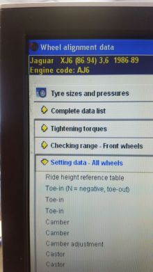
Jaguar Wheel Alignment Data (from Jaguar dealership see below)
This is helpful, it gives the data 3 ways and clears up a bit of mystery/ambiguity I think.
Toe in mm 0.8 (+/-0.8)
Toe in deg 0.10 +/- 0.10
Toe in deg 0°6’ +/- 6’
I’m going to assume all of these measurements are a combined measurement (ie the total toe between the wheels), so a toe of 10 mins would mean 5 mins at each wheel. Therefore, I’ll aim at 5 minutes/side. Jag data specifies anything between zero and 12mins combined (zero and 6 mins per side).GDs figure of 10 minutes refers to combined toe so that’s 5 minutes per side… Voila everything’s on the same page more or less, I’m happy and your bored!

Rather than try to measure 0.8mm over 15” it is much easier to set up a string line system (fine thread or braid is great for this) to measure 3mm over 2.4m (which is a nice distance to gauge an accurate setting), and conveniently is the approx. distance between centreline of rear axle and steering rack so easy to set up a nice square. I have to comment at this stage on the accuracy of the Chassis – so far I have been extremely impressed at the accuracy obtained in manufacturing the chassis, which translates into very little and even shimming of running gear components. I know how difficult this kind of accuracy is to achieve – so “hats off” to GD for their Jig work!

Couple or recommendations here.
1 – make absolutely sure that the straight edge you use to clamp to the disc, which acts as the alignment throw for the toe measurement, is absoluteley straight and perfectly clamped to the disc. Any tiny amount ‘out of true’ for your staraight edge will make this measurement useless.
2 To adjust the toe use shims between the wishbone carrier bracket and the diff to achieve the desired toe of -3mm at 2.4m away – but I would suggest removing the GD back carrier bracket before making these adjustments. It was my experience that the holes in this bracket are very “tied up” to the shaft diameter therefore it was impossible to correctly adjust the toe with this bracket in place. All you would be doing is inducing stress into the shaft and needle bearings in the wishbone bush. Once the correct toe is achieved offer the bracket back in place and make any adjustments to the holes filing as necessary. On my set up slight slotting of the holes was necessary to enable perfect fit and inducing no sideway out of alignment stresses onto the shaft ends. Only then torque this back bracket back into position.


