Setting the bumpsteer was interesting I firstly tried clamping straight edges and using line of sight to keep them parallel. This did identify how far out it was to begin with (quite a bit) but I didn’t feel confident about achieving the best position this way since it was difficult to perceive very small changes.
Out with the trusty Hilti Laser (this is a self-levelling type of laser so I clamped that on the wheel disk fired straight ahead, in the direction of travel onto the garage door a few feet away. After some plotting of curves it quickly becomes obvious that you can’t really do it this way since the observed travel is a combination of bumpsteer together with scrub (the in/out movement of the wheels caused by the wishbone radiuses) and camber change effect (caused by the unequal wishbone lengths).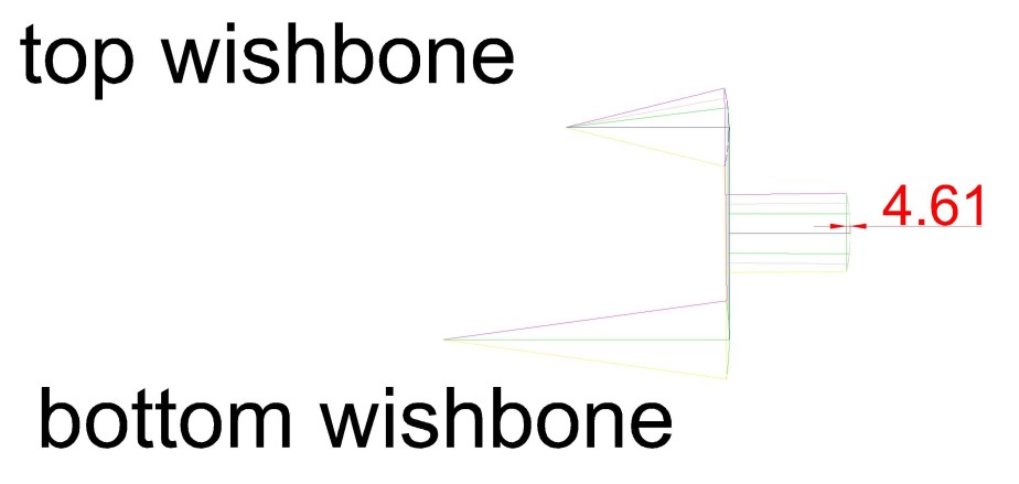
You could use the above method by calculating the amount of scrub then plotting the curve that is created by the radius arm travel Then whilst measuring bumpsteer the best line that could be achieved is the compound curve shown above right. But even then you would also need to account for the camber change that is happening throughout this movement.
The method of shooting the laser perpendicular to the wheel disc is better because this eliminates the scrub effect since the laser will not move “off line” due to scrub, it moves off line only due to bumpsteer. ( plus a bit of vertical change due to camber change).
You could use a mirror clamped flat to the disk and fire the laser at the mirror as has been suggested before but I’m not convinced what the mirror brings to the party, I feel it just complicates the setup.
With a couple of simple clamps fixing the laser approximately perpendicular to the disc at any point will allow exceptionally accurate readings to be made very swiftly – horizontal movement of the laser line only represents the element being induced by the steering arm…. Job done.
The further away you can put the target the better since any slight movement is exaggerated, in my case I was able to get an almost vertical line at 4m distance that’s definitely zero bumpsteer (well near enough). Again well done GD for excellent geometry around the steering rack chassis elements. This would not be possible unless everything was in excellent geometric harmony.
Ok that’s the end of this boring bit (Civil Engineers white helmet off – petrol head back in place…..)
Did I mention I was impressed with GD’s chassis geometry J?
As you can see I have been rather milking this part of the build simply because I have no other parts… However things should start getting real busy soon. Just had confirmation my engine gearbox clutch atc are all arriving next week then i can start with engine installation wiring etc. plus body is still on schedule for early May so lots of action coming shortly..

Just testing! Are you a mathmatician? I am glad I didn’t have to sort out the bumpsteer after reading this!
LikeLike